Products Description
| Company Information | |||
| [email protected] | |||
| Mobile | +8613666033393 | ||
| +8613666033393 | |||
| 13666033393 | |||
| Add | Room 1004, No. 62 Xiangxiu Li, Siming District, Xiamen City, Fujian Province, China |

Technical Specifications
| Parameter | Specification |
|---|---|
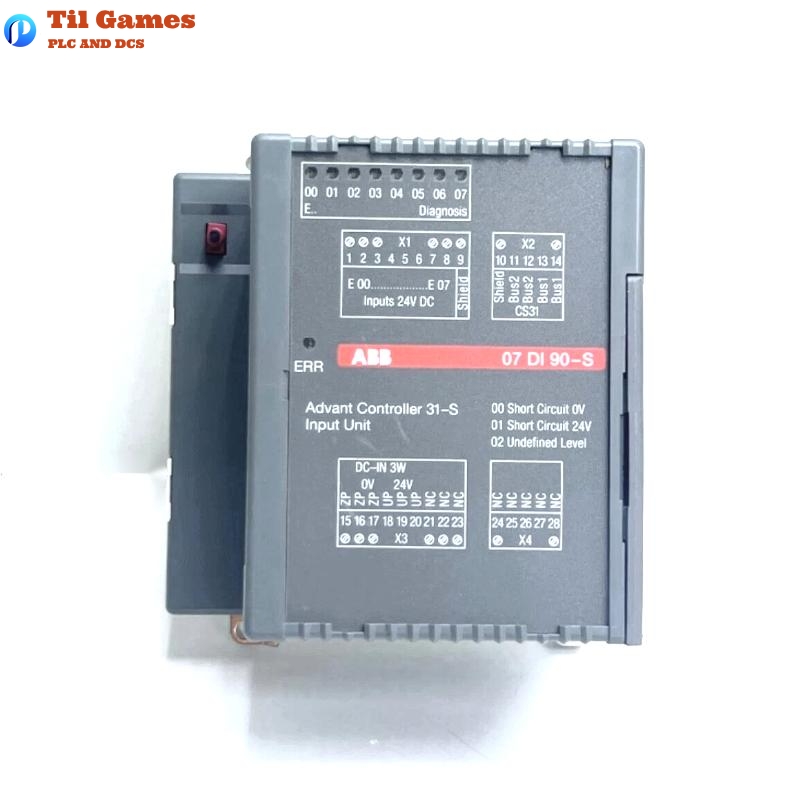
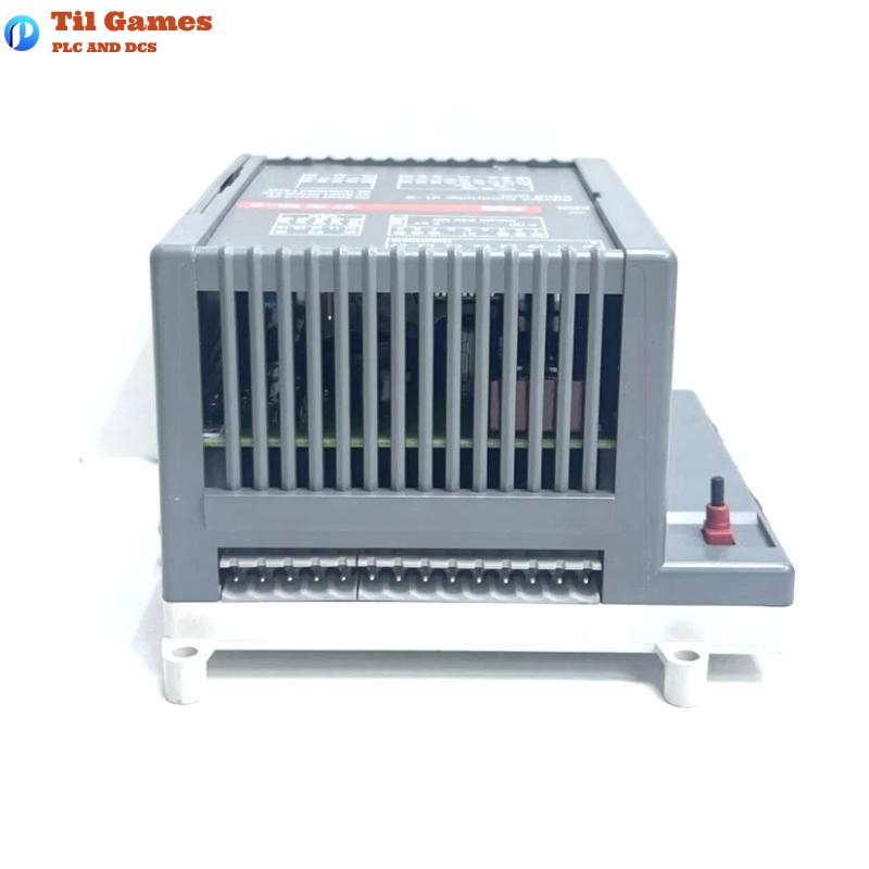
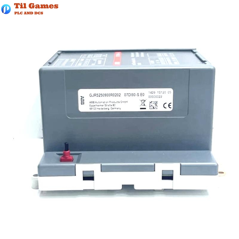
| Product Type | Digital Input Module (Binary Input) |
| System Compatibility | Advant Controller 31-S (AC31-S) |
| Input Channels | 8 inputs for 24 V DC safety-related sensors |
| Input Voltage (Nominal) | 24 V DC ±5% |
| Upper Limit Voltage | 28.8 V DC (24 V + 20%) |
| Lower Limit Voltage | 20.4 V DC (24 V – 15%) |
| Buffered Voltage Interruption Time | > 10 ms |
| Input Resistance | Approx. 2.2 kΩ |
| Input Current | Approx. 10 mA at 24 V DC |
| Signal Delay (0 → 1 / 1 → 0) | Typ. 5 ms, monitored up to 20 ms |
| Max Input Frequency | 20 Hz |
| Signal Transition Time | 0 ms to 5 ms |
| Signal Level Definitions | 0: 3.6–8.4 V, 1: 15.6–20.4 V, short-circuits: <3.6 V or >20.4 V |
| Electrical Isolation | Yes, from CS31 bus via reinforced insulation |
| Rated Insulation Voltage | 0–50 V DC |
| Test Voltage | 800 V DC |
| LED Indicators | 8 yellow LEDs for inputs, 1 red LED for error |
| Module Address Setting | DIL switch (0–31) |
| Safety Function | Dual-channel signal processing with fault detection |
| Cable Length (Shielded) | Max. 1000 m |
| Cable Length (Unshielded) | Max. 600 m |
| Conductor Cross Section | Max. 1 × 2.5 mm² |
| Tightening Torque | Max. 0.5 Nm |
| Power Consumption | 110 mA (UP), Max. 3 W |
| CS31 Bus Transmission Time | 590 µs |
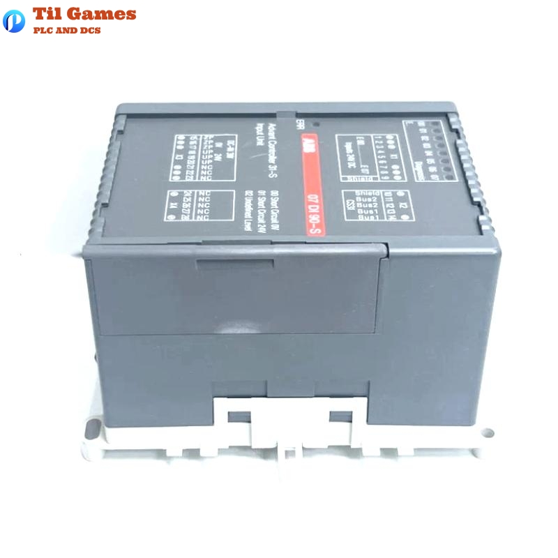
| Installation Method | DIN rail mounting or screw mounting |
| Mounting Position | Vertical, terminals up and down |
| Cooling | Natural convection, no obstruction allowed |
| Dimensions (W x H x D) | 120 × 140 × 85 mm |
| Weight | 0.81 kg |
FAQ
Frequently Asked Questions (FAQ)
Q1: What is the function of the ABB 07DI90-S module?
A1: The 07DI90-S is a digital input module with 8 channels designed for safety-related applications. It detects signal states and differentiates faults such as wire cuts and short circuits using dual-channel processing.
Q2: How is the module connected to the control system?
A2: The module connects to the central controller (07 KT 94-S) via the CS31 system bus. Electrical isolation is maintained between the system bus and the input channels.
Q3: What types of sensors can be connected to the input channels?
A3: The module is intended for 24 V DC safety-related sensors. These must be supplied from the same power rail (UP) as the module to ensure accurate signal state differentiation.
Q4: How are module addresses configured?
A4: The address is set using a DIL switch located beneath the module’s cover. Switches 3 to 7 represent binary address bits with a range from 0 to 31.
Q5: How are errors detected and indicated?
A5: The module distinguishes between internal and external errors. External faults like wire cuts or overvoltage are indicated via a flashing red LED, while internal faults cause the red LED and all channel LEDs to stay lit.
Q6: What happens during startup?
A6: Upon power-up, the module performs a self-test. The red error LED lights up for approximately 10 seconds, then flashes until the module is adopted into the CS31 bus cycle.
Q7: How should unused inputs be handled?
A7: Unused input channels must be pulled up to +24 V using two resistors (680 Ω and 5.6 kΩ in series) to prevent fault indication due to floating inputs.
Q8: What is the required installation method and mounting position?
A8: The module can be DIN rail mounted or screwed directly into the control cabinet. It must be installed vertically with terminals at the top and bottom to allow proper convection cooling.
Tags
Packing & Delivery
We will use wear-resistant cartons to seal the boxes, and take photos for your confirmation before sealing. We will pack the boxes only after confirmation.
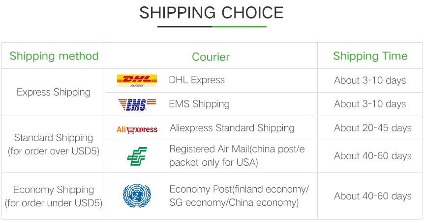
For express delivery, we will use DHL, UPS, TNT, FedEx and EMS.
Please rest assured that we have a deep cooperation with express delivery companies and can ensure that your goods are delivered to you in good condition.